
 +86-28-85980596
  sales@xtaltq.com
Phase Noise Test: Method and Procedure for Accurate Measurement of Crystal Oscillators
Phase noise is a critical parameter in the performance evaluation of crystal oscillators. It provides a measure of the timing accuracy and jitter in the oscillator output, which are crucial for applications such as frequency synthesis, signal generation, and clock distribution in communication systems. In this article, we will discuss the phase noise test method and procedure for accurately measuring crystal oscillators.
1. Introduction to Phase Noise
Phase noise is a measure of the instability in the frequency or phase of a periodic signal. It is caused by the random fluctuations in the oscillator output frequency, resulting in a degradation of the signal quality. Phase noise can be characterized in terms of its power spectrum density (PSD), which represents the power density of noise versus frequency offset from the carrier frequency.
Crystal oscillators are widely used in various electronic systems due to their high frequency stability and low phase noise. Phase noise is a measure of the random frequency fluctuations present in the oscillator's output. It is caused by various internal noise sources within the oscillator, such as thermal noise, shot noise, and flicker noise. Phase noise can also be affected by external factors, such as aging, temperature changes, and environmental effects.
2. Test Setup for Phase Noise Measurement
The phase noise test setup typically consists of a signal source to generate an excitation signal, a mixer to convert the signal to an intermediate frequency (IF), and a phase noise analyzer to measure the phase noise power spectrum. The active crystal oscillator to be tested is connected to the signal source, and its output is fed to the mixer, which converts it to an intermediate frequency. The IF signal is then fed to the phase noise analyzer for measurement of phase noise.
To accurately measure the phase noise of crystal oscillators, the following two points must be noted:
2.1. Test Environment
The test environment should be controlled to minimize external interference and noise sources that could affect the phase noise measurement. This includes shielding the test setup from electromagnetic interference (EMI), controlling temperature fluctuations, and minimizing vibrations.
2.2. Test Equipment
High-quality test equipment is essential for accurate phase noise measurements. This includes a high-frequency signal generator, a power supply, a frequency counter, and a phase noise analyzer. The signal generator should have low phase noise and be able to generate a clean reference signal for the crystal oscillator. The power supply should provide stable voltage and current to the oscillator, and the frequency counter should have high resolution and accuracy. The phase noise analyzer is used to measure the phase noise power spectrum of the oscillator's output.
3. Test Procedure for Phase Noise
The following steps outline the procedure for accurate measurement of phase noise in crystal oscillators:
Step 1: Set up the test equipment and ensure proper connections between the signal source, mixer, phase noise analyzer, and the active crystal oscillator.
Step 2: Adjust the frequency of the signal source to match the desired operating frequency of the active crystal oscillator.
Step 3: Adjust the mixer to convert the oscillator output to an appropriate intermediate frequency. This frequency should be within the range of the phase noise analyzer.
Step 4: Connect the phase noise analyzer to the mixer output and set it to measure phase noise.
Step 5: Acquire and record the phase noise power spectrum data from the phase noise analyzer. The data can be plotted as a function of frequency offset from the carrier frequency.
Step 6: Analyze the phase noise power spectrum data to determine key phase noise parameters such as offset frequency, power level, and spectral density. These parameters provide a quantitative assessment of the oscillator's phase noise performance.
4. Example Phase Noise Test Results
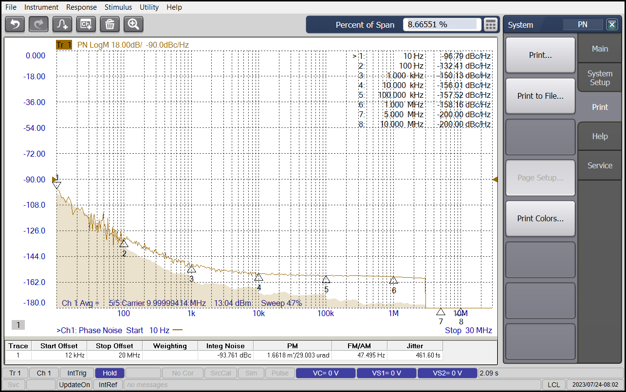
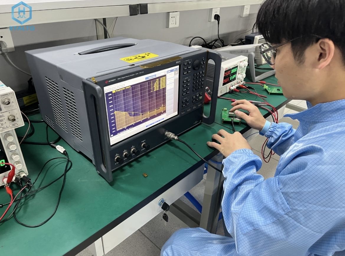
In this example, our R&D team member will use a piece of TCXO produced by XtalTQ Technology Co., Ltd. to give a phase noise test result with a center frequency of 10 MHz. The test device is composed of signal source, mixer, phase noise analyzer and a piece of TCXO. The power spectrum of phase noise measured by a standard frequency 10MHz oscillator is shown below:
The figure shows the noise power density as a function of the frequency deviation from the carrier frequency. The curve shows that at the offset frequency of 10Hz, the oscillator's peak phase noise power density is -96.79 dBc/Hz@10Hz, -132.41 dBc/Hz@100Hz, and -150.13dBc/Hz@1kHz.
5. Conclusion
The phase noise test method and procedure outlined in this article provide a means to accurately measure the phase noise performance of crystal oscillators.
By following the steps outlined in the procedure and analyzing the resulting phase noise power spectrum data, key parameters such as offset frequency, power level, and spectral density can be extracted to assess the oscillator's performance. This information is crucial for applications where precise frequency control and low jitter are critical, such as in communication systems, timing systems, and frequency synthesis applications. By following the recommended test method and procedure outlined in this article, test engineers can accurately measure phase noise and ensure optimal performance of crystal oscillators in their systems.
Thank you!
 +86-28-85980596
 sales@xtaltq.com
 No.666 Shaojia Street, Shuangliu District, Chengdu, China


